 A Circlotron is a vacuum tube power amplifier with an unusual
push-pull output stage. Rather than alternately driving halves of
an output transformer primary whose center-tap is connected to B+,
a Circlotron drives the entire primary from a floating bridge.
Originally, Circlotron was an Electro-Voice (EV) trademark, these
days it seems to refer to any amplifier with a bridged output stage
and floating power supplies.
A Circlotron is a vacuum tube power amplifier with an unusual
push-pull output stage. Rather than alternately driving halves of
an output transformer primary whose center-tap is connected to B+,
a Circlotron drives the entire primary from a floating bridge.
Originally, Circlotron was an Electro-Voice (EV) trademark, these
days it seems to refer to any amplifier with a bridged output stage
and floating power supplies.| Model |
Output Power |
Output Tubes |
Output Transformer Primary Impedance |
Photo |
| A15 |
15 Watt |
(2) EL84 |
2000 Ohm CT |
A15 |
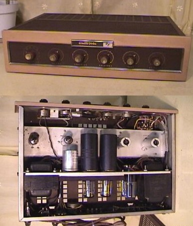
| A15CL -
Lowboy Integrated Preamp |
15 Watt |
(2) EL84 |
2000 Ohm CT |
A15CL |
| A20 |
20 Watt |
(2) 6V6 |
2000 Ohm CT |
A20 |
| A20CL -
Lowboy Integrated Preamp |
20 Watt |
(2) 6V6 |
2000 Ohm CT |
A20CL |
| A20C -
Integrated Preamp |
20 Watt |
(2) 6V6 |
2000 Ohm CT |
A20C |
| A30 (early production) |
30 Watt |
(2) 6BG6 |
1000 Ohm CT |
Early A30 |
| A30 (late production) |
30 Watt |
(2) 1614 |
1600 Ohm CT |
Late A30 |
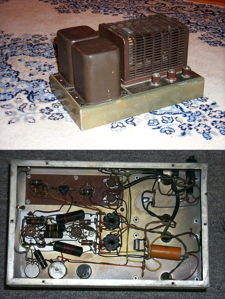
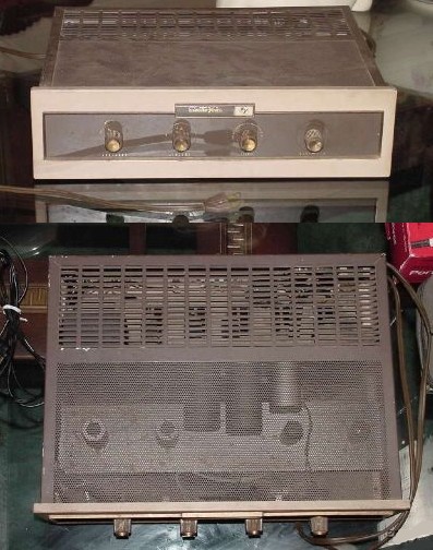
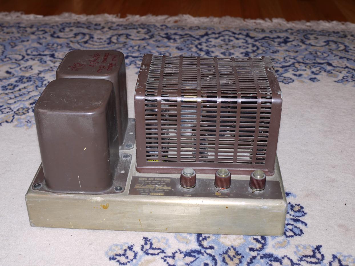
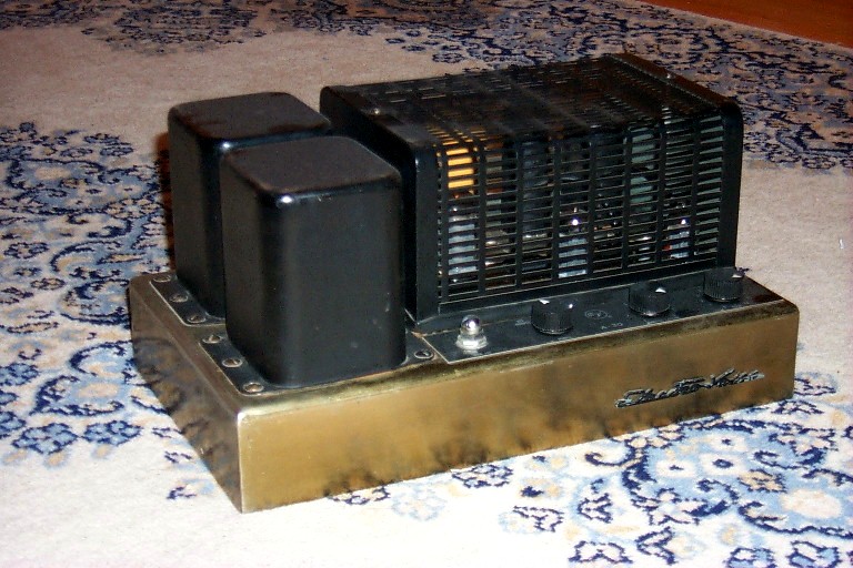
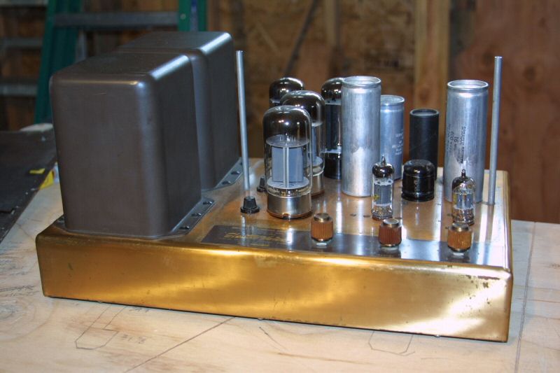
| A50 |
50 Watt |
(2) 6550 |
1200 Ohm CT |
A50 |
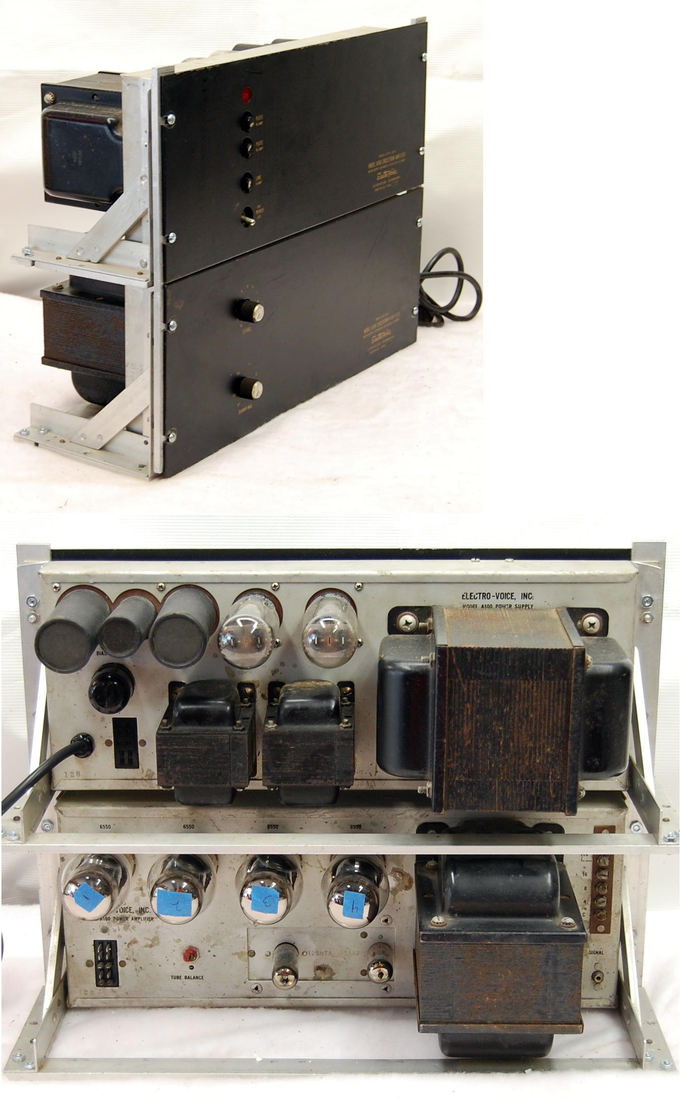
| A100 (early production) |
100 Watt |
(4) 6550 |
600 Ohm CT |
Early A100 |
| A100 (late production) |
100 Watt |
(4) 6550 |
600 Ohm CT |
Late A100 |
| Model |
Output Power |
Output Tubes |
Photo |
| A2-20 |
20 Watt |
(2) EL84 |
A2-20
|
| Model |
Output Power |
Output Tubes |
Photo |
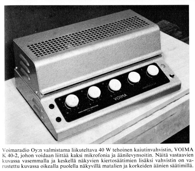
| AG 9006, AG 9006 Service |
20 Watt |
(2) EL81 |
AG9006
|
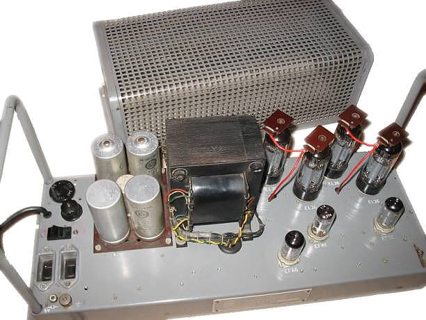
| AG 9007 |
60 Watt |
(4) EL36 |
AG9007
|
| Model |
Output Power |
Output Tubes |
Photo |
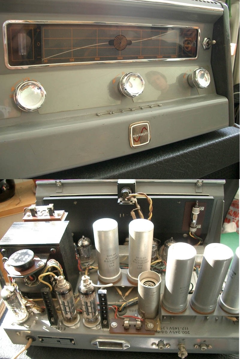
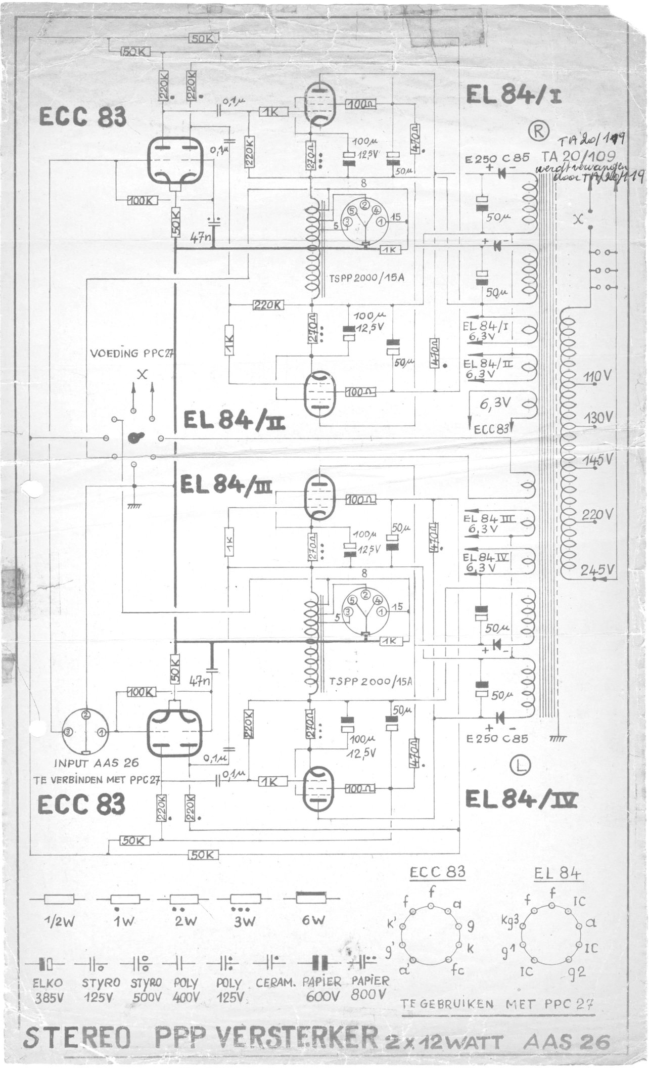
| AAS26 |
12 Watt |
(2) EL84 per channel |
AAS26
|
| AS16 |
?? Watt |
(2) EL34 |
AS16
|
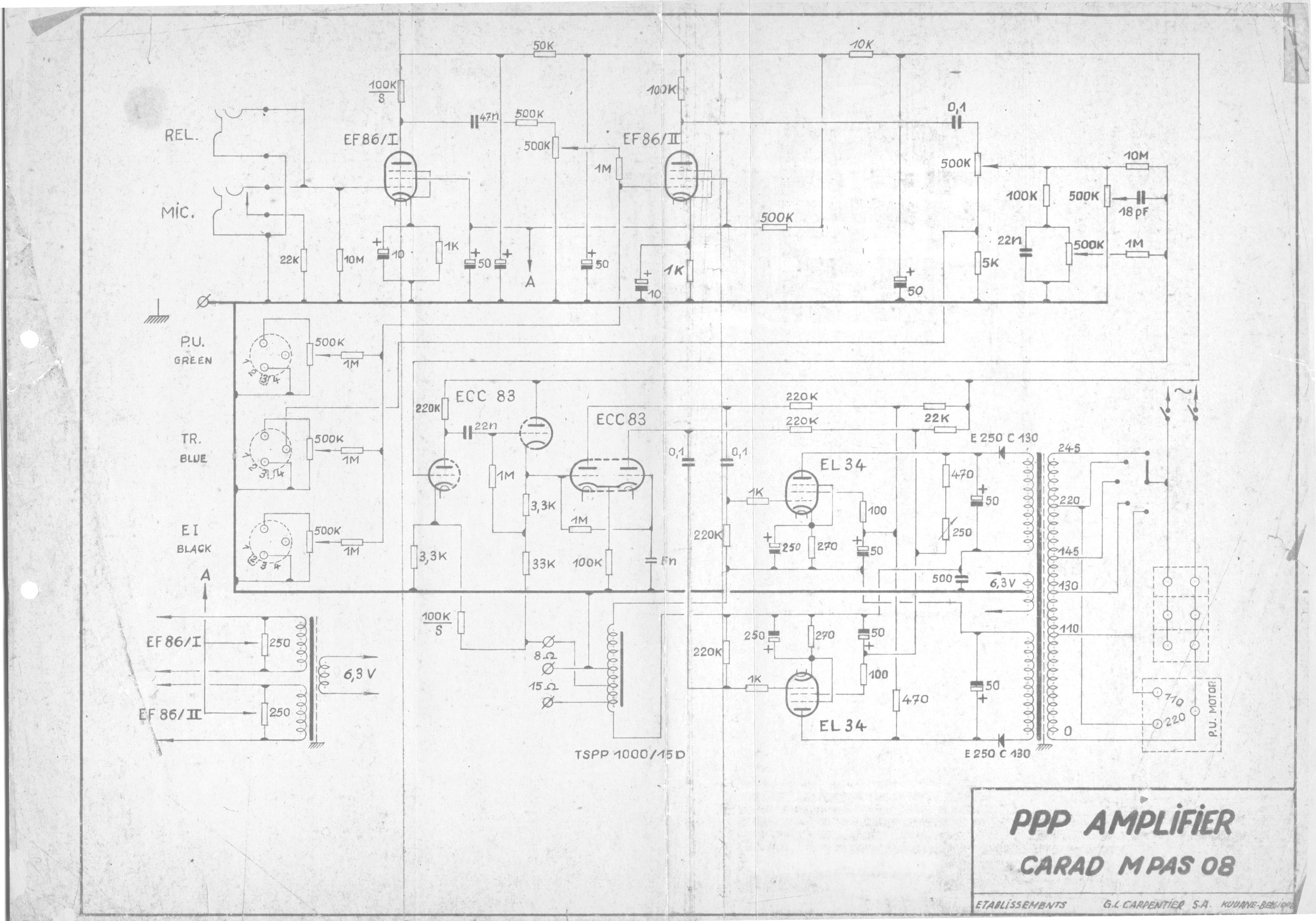
| MPAS08 |
?? Watt |
(2) EL34 |
MPAS08
|
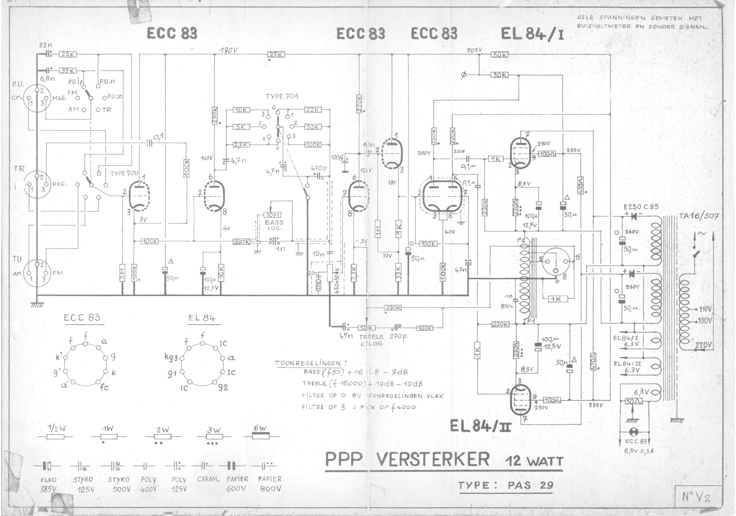
| PAS29 |
12 Watt |
(2) EL84 |
PAS29
|
| Model |
Output Power |
Output Tubes |
Photo |
| PIC-35 |
?? Watt |
(2) EL34 per channel |
PIC-35
|